Why is Arduino digitalWrite So Slow?
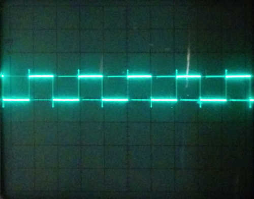
I got an Arduino Uno for Christmas this year and I've been playing around with it a little bit over the last few days. While trying to get a simple PWM program to work, I noticed that it starts acting weird at higher frequencies. The square wave actually produced by the microcontroller drifts farther and farther away from the expected signal the higher the frequency gets. Here's some oscilloscope output to show you what I mean. All of the signals should be 5 Vp-p and have a 50% duty cycle. The scope is set to 5V/div in every image.
PWM Output
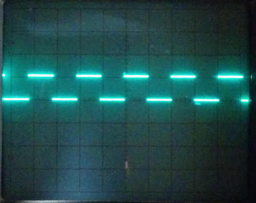
1 kHz, 500 µs/division
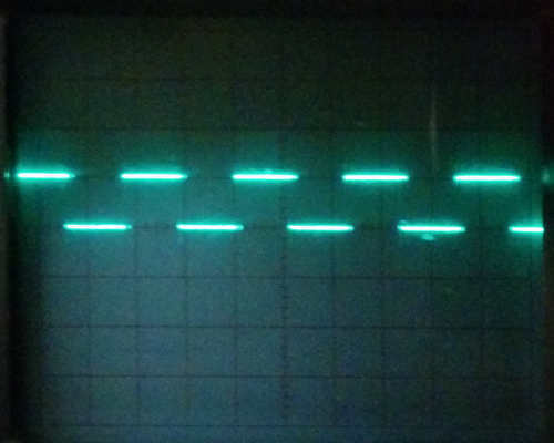
10 kHz, 50 µs/division
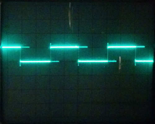
100 kHz, 10 µs/division
Even using my terrible oscilloscope, it's pretty clear that something is going on that causes the timing to be way out at higher frequencies. The 100 kHz signal should take up one division at that timebase, but instead it takes four (the Gibbs phenomenon is probably just due to the low bandwidth of my scope). So, what could be going on that makes the Arduino spend 20 µs on each transition?
First of all, here's the code I used to generate these figures:
/*

  Very, very, very basic PWM test code

*/


int pwm_pin = 4;                       // Pin to output the signal on

long int pwm_freq = 100e3;             // PWM frequency in Hz

int period = int(1e6/float(pwm_freq)); // Period of the PWM signal in microseconds

int half_period = period/2;            // Half the PWM period in microseconds


// Set up our pin

void setup() {

  // Output mode

  pinMode(pwm_pin, OUTPUT);

}


// Do this forever

void loop() {

  digitalWrite(pwm_pin, HIGH);     // Output high

  delayMicroseconds(half_period);  // Wait half a period

  digitalWrite(pwm_pin, LOW);      // Output low

  delayMicroseconds(half_period);  // Wait half a period

}
You can see it's pretty basic; it just uses digitalWrite to switch pin 4 from high to low halfway through each period. At first I thought that maybe the problem was in delayMicroseconds, but the Arduino documentation says this should be accurate down to 3 µs, so it shouldn't have a problem at 100 kHz (5 µs between transitions). The only other function I call on every loop iteration is digitalWrite, so the problem must lie there. I Googled around and, sure enough, lots of other people have encountered this behavior.
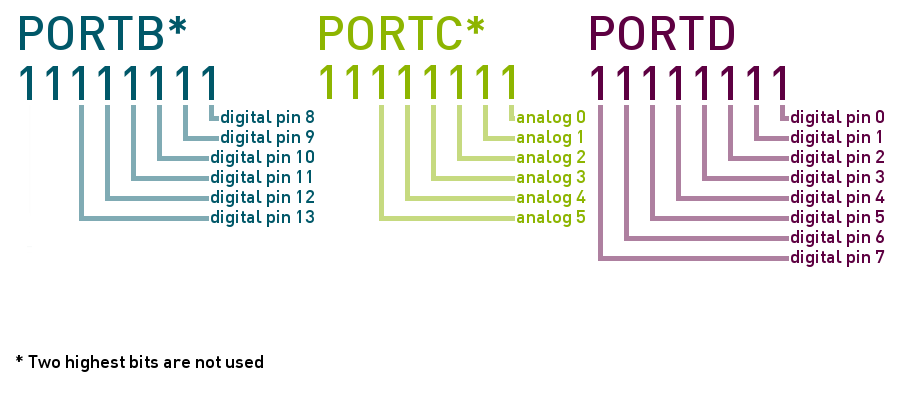
There is another technique we can use to write to the digital pins on the Arduino board. Instead of digitalWrite, I tried using the port registers directly. This is much more complicated and brittle, but there's no other way that I could find to get high-speed signals to come out of the digital I/O pins. The AVR microcontrollers used on the Arduino boards have three 8-bit registers called PORTB (digital pins 0-7), PORTC (analog pins 0-5), and PORTD (digital pins 8-13) that correspond to the physical analog and digital pins on the board. I made a diagram to explain:
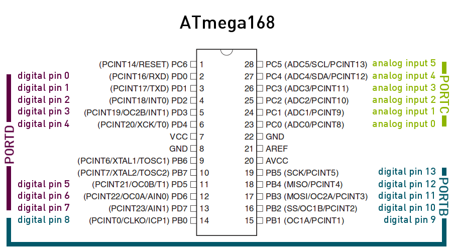
Each of the eight bits in the register corresponds to a pin. For example, in the register that contains digital pin 4, PORTD, the lowest bit corresponds to pin 0, the next bit corresponds to pin 1, etc. Here are some more diagrams to help explain:
So, for the equivalent of digitalWrite(4, HIGH);, we need to set pin 4 to 1 and for digitalWrite(4, LOW);, we need to set it to 0. The PORTD variable contains all eight bits in the register, so we'll have to make sure not to upset the other bits when we assign a value to the register. We can do this by using C's bitwise operators on the PORTD variable, like this:
PORTD |= B00010000;

PORTD &= B11101111;
You can see that we used two different numbers to manipulate the PORTD variable. In the first line, we OR every bit except number 4 with 0, leaving their values unchanged. We OR bit 4 with 1, making its value 1, or HIGH. In the second line, we do basically the opposite, ANDing every bit except 4 with 1, which doesn't change their values, and ANDing bit 4 with 0, setting its value to 0 or LOW.
The nice thing about this way of manipulating the pins is that you can change more than one pin at once. For example, if I wanted to set pins 3, 5, and 7 to high, I could write:
PORTD |= B10101000;
Or, if I want to set pins 2, 3, and 6 high, I can do
PORTD |= B01001100;
I can also switch every pin off at once by writing
PORTD &= B00000000;
or even
PORTD = 0;
Here, then, is what my loop() function looked like using PORTD instead of digitalWrite. Note that I used hex instead of binary in my code, but the values are the same.
void loop() {

  PORTD |= 0x10;                   // Set pin 4 to 1

  delayMicroseconds(half_period);  // Wait half a period

  PORTD &= 0xef;                   // Set pin 4 to 0

  delayMicroseconds(half_period);  // Wait half a period

}
And here's what the output signal looks like:
100 kHz, 5 µs/division
That's more like it. Each half of the square wave takes exacly 5 µs, which is exactly what we expect for a 100 kHz signal with a 50% duty cycle. Obviously, using the port register is much, much faster than using digitalWrite, but why?
Disassembling Some Binaries
To find out, I thought I might try to disassemble the binaries that get put on the Arduino. I did this on Ubuntu (apt-get install arduino arduino-core), but all the same tools should come with the Windows and Mac versions of the Arduino IDE.
On Linux, the Arduino IDE stores binaries generated by the verify button in /tmp/build*.tmp/. In this folder, there should be an ELF file that contains the object code. The Arduino package includes special AVR versions of a bunch of binutils, so I used avr-objdump to get a look at the assembly code. Specifically, avr-objdump -d <YOUR FILE>.cpp.elf will give you the assembly from the object file.
Virtually all of the code is the same in both versions of the program, so I'll focus on the parts that are significantly different: the loop function and the digitalWrite function itself. First, here is the assembly for the loop function in both versions of the code, digitalWrite on the left, and port registers on the right:
00000118 <loop>:

 118:	cf 93       	push	r28

 11a:	df 93       	push	r29

 11c:	c4 e0       	ldi	r28, 0x04	; 4

 11e:	d1 e0       	ldi	r29, 0x01	; 1

 120:	61 e0       	ldi	r22, 0x01	; 1

 122:	88 81       	ld	r24, Y

 124:	0e 94 2c 01 	call	0x258	; 0x258

 128:	80 91 06 01 	lds	r24, 0x0106

 12c:	90 91 07 01 	lds	r25, 0x0107

 130:	0e 94 ac 01 	call	0x358	; 0x358

 134:	60 e0       	ldi	r22, 0x00	; 0

 136:	88 81       	ld	r24, Y

 138:	0e 94 2c 01 	call	0x258	; 0x258

 13c:	80 91 06 01 	lds	r24, 0x0106

 140:	90 91 07 01 	lds	r25, 0x0107

 144:	df 91       	pop	r29

 146:	cf 91       	pop	r28

 148:	0c 94 ac 01 	jmp	0x358	; 0x358
00000104 <loop>:

 104:	5c 9a       	sbi	0x0b, 4	; 11

 106:	80 91 06 01 	lds	r24, 0x0106

 10a:	90 91 07 01 	lds	r25, 0x0107

 10e:	0e 94 37 01 	call	0x26e	; 0x26e

 112:	5c 98       	cbi	0x0b, 4	; 11

 114:	80 91 06 01 	lds	r24, 0x0106

 118:	90 91 07 01 	lds	r25, 0x0107

 11c:	0c 94 37 01 	jmp	0x26e	; 0x26e
Well. I was surprised at how much shorter the code is when you take out those digitalWrites, but it makes a lot of sense when you break it down. First I'll briefly explain what the code does without digitalWrite since it's shorter.
Using the Port Registers
The first line, sbi 0x0b, 4 is exactly equivalent to the line PORTD |= 0x10 in the C source. The instruction sdi A,b sets bit b in register A to 1, so sdi 0x0b, 4 sets bit 4 in register 11 (the PORTD register) to 1. Easy.
The next three lines set up our call to delayMicroseconds. The lds Rd, k instruction is a load instruction; it puts the value in SRAM at address k onto register Rd. In this code, we're loading the values at 0x0106 and 0x0107 into registers 24 and 25, respectively. Then, we call the function at 0x26e, which is delayMicroseconds.
After that, we see the instruction cbi 0x0b, 4. This should look familiar; it's the opposite of the sdi instruction. This particular instruction sets the value of bit 4 in register 11 to 0.
After that, we have another call to delayMicroseconds (using jmp instead of call) and the loop repeats.
Using digitalWrite
The digitalWrite version of the code is a little more than twice as long as the port register version, so let's take a look at the parts that are different.
Right off the bat, we have two push instructions. These instructions push the named registers onto the stack, in this case registers 28 and 29. For the unfamiliar, the stack is basically a structure that allows values to be stored in the much larger SRAM rather than in the comparatively small registers. The push instructions here put the values in registers 28 and 29 into memory somewhere so that they can be retrieved later (for example, the two pop instructions at the end of the function do this). Elsewhere in the program these values were initialized to 0, so those values are added to the stack at this point.
So, following these two push instructions, we have two ldi instructions. These are load instructions just like the lds we saw earlier, but they load a constant value onto a register rather than loading a value from SRAM. Here, we're loading the values 4 and 1 into registers 28 and 29, which we'll talk about next. After this, we load the value 1 into register 22.
The next line, ld r24, Y is a little complicated. It's a load instruction, so it puts a value from memory into the named register. The interesting thing about this instruction is the special value Y. There are three of these values, X, Y, and Z. Each one refers to a pair of registers; r26 and r27 for X, r28 and r29 for Y, and r30 and r31 for Z. Each pair refers to a 16-bit memory address with the high byte in the higher register and the low byte in the lower one. In this case, we're loading the value at address 0x0104 (r28 and r29) into register r24. This value is used by digitalWrite to determine which port register it needs to write to, but we'll get to that in a bit.
After that, things are largely the same as in the code that uses port registers. We next load the values at 0x106 and 0x0107 into r24 and r25 and call delayMicroseconds. After that, we repeat the indirect load into r24 and call digitalWrite again before calling delayMicroseconds for a final time.
What Does digitalWrite Do?
This is the complicated part. The digitalWrite function looks like this:
00000258 <digitalWrite>:

 258:	0f 93       	push	r16

 25a:	1f 93       	push	r17

 25c:	cf 93       	push	r28

 25e:	df 93       	push	r29

 260:	1f 92       	push	r1

 262:	cd b7       	in	r28, 0x3d	; 61

 264:	de b7       	in	r29, 0x3e	; 62

 266:	28 2f       	mov	r18, r24

 268:	30 e0       	ldi	r19, 0x00	; 0

 26a:	f9 01       	movw	r30, r18

 26c:	e8 59       	subi	r30, 0x98	; 152

 26e:	ff 4f       	sbci	r31, 0xFF	; 255

 270:	84 91       	lpm	r24, Z

 272:	f9 01       	movw	r30, r18

 274:	e4 58       	subi	r30, 0x84	; 132

 276:	ff 4f       	sbci	r31, 0xFF	; 255

 278:	14 91       	lpm	r17, Z

 27a:	f9 01       	movw	r30, r18

 27c:	e0 57       	subi	r30, 0x70	; 112

 27e:	ff 4f       	sbci	r31, 0xFF	; 255

 280:	04 91       	lpm	r16, Z

 282:	00 23       	and	r16, r16

 284:	c9 f0       	breq	.+50     	; 0x2b8

 286:	88 23       	and	r24, r24

 288:	21 f0       	breq	.+8      	; 0x292 <digitalWrite+0x3a>

 28a:	69 83       	std	Y+1, r22	; 0x01

 28c:	0e 94 ca 00 	call	0x194	; 0x194

 290:	69 81       	ldd	r22, Y+1	; 0x01

 292:	e0 2f       	mov	r30, r16

 294:	f0 e0       	ldi	r31, 0x00	; 0

 296:	ee 0f       	add	r30, r30

 298:	ff 1f       	adc	r31, r31

 29a:	ec 55       	subi	r30, 0x5C	; 92

 29c:	ff 4f       	sbci	r31, 0xFF	; 255

 29e:	a5 91       	lpm	r26, Z+

 2a0:	b4 91       	lpm	r27, Z

 2a2:	9f b7       	in	r25, 0x3f	; 63

 2a4:	f8 94       	cli

 2a6:	8c 91       	ld	r24, X

 2a8:	61 11       	cpse	r22, r1

 2aa:	03 c0       	rjmp	.+6      	; 0x2b2 <digitalWrite+0x5a>

 2ac:	10 95       	com	r17

 2ae:	81 23       	and	r24, r17

 2b0:	01 c0       	rjmp	.+2      	; 0x2b4 <digitalWrite+0x5c>

 2b2:	81 2b       	or	r24, r17

 2b4:	8c 93       	st	X, r24

 2b6:	9f bf       	out	0x3f, r25	; 63

 2b8:	0f 90       	pop	r0

 2ba:	df 91       	pop	r29

 2bc:	cf 91       	pop	r28

 2be:	1f 91       	pop	r17

 2c0:	0f 91       	pop	r16

 2c2:	08 95       	ret
Ugh. This one is 54 lines, which is a bit more than I care to analyze a line at a time. Briefly, digitalWrite starts by checking whether a valid pin number was provided. It then determines whether PWM is enabled on the pin and disables it if it is. Next, it determines which port register contains the given pin (register 24) and sets its value to HIGH or LOW (register 22). This ends up requiring 54 lines of assembly, not including the 35 lines required for the potential call to turnOffPWM and the extra 10 lines of assembly added to our main loop. This is compared to 1 line of assembly if we want to write directly to the port register ourselves.
Some Actual Numbers
So, the ATmega168 on the Arduino Uno board is clocked at 16 MHz, which means that (generously assuming an average of 1 cycle per instruction), each instruction will take 62.5 ns. This means that we should expect a call to digitalWrite to take somewhere between 3 µs and 6 µs, depending on whether or not turnOffPWM is called. Writing to the port register, on the other hand, should take about 125 ns since the sbi and cbi instructions each take two clock cycles. This is enough to account for the timing issues we saw at 100 kHz, but I thought I'd measure it anyway to see what the difference actually is. Here's a table I made by timing and averaging 1,000,000 calls to digitalWrite and 1,000,000 port register manipulations:
| Method | Time (ns) |
|---|---|
| digitalWrite | 6005 |
| Port Register | 440 |
There's some overhead from the for loop I used, but the conclusion is still the same: writing directly to the port register is a little more than an order of magnitude faster than using digitalWrite. You sacrifice a lot of flexibility, but if you need to switch the digital pins faster than once every few microseconds it's really the only option.